
Worm gear speed reducers are often chosen for one reason: control. In the right application, their ability to hold load without back‑driving can be a major advantage. In the wrong one, that same feature can work against performance, efficiency, or long-term reliability.
Self‑locking isn’t inherently good or bad, it’s situational. Understanding when worm gear self-locking is an asset and when it becomes a liability is critical for engineers, OEMs, and equipment designers tasked with building safe, durable systems that perform as expected in the field.
This article breaks down how worm gear speed reducers work, what self-locking actually means in real applications, and how to decide whether this design is the right fit for your equipment.
What Is a Worm Gear Speed Reducer?
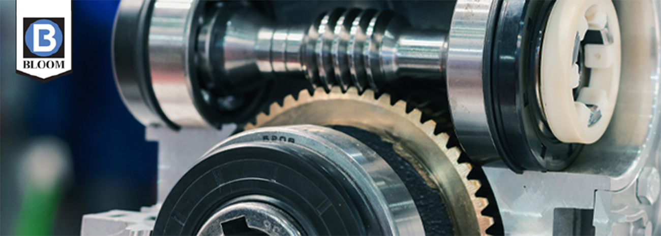
A worm gear speed reducer uses a screw‑like input shaft (the worm) that meshes with a larger gear (the worm wheel). The worm drives the wheel at a right angle, producing significant speed reduction and torque multiplication in a compact package.
This design naturally supports:
- High reduction ratios
- Smooth, controlled output motion
- Compact installation in tight mechanical layouts
Because of the sliding contact between the worm and wheel, worm reducers also behave differently than spur, helical, or planetary designs, namely when load forces try to drive the system in reverse.
Understanding Self‑Locking in Worm Gears
Self‑locking occurs when the worm gear cannot be back‑driven by load forces acting on the output shaft. In simple terms, the input can turn the output, but the output cannot turn the input.
This happens when friction between the worm and gear exceeds the force generated by the load attempting to reverse the system. Factors that influence self‑locking include:
- Lead angle of the worm
- Gear ratio
- Surface finish
- Lubrication
- Load magnitude
Lower lead angles and higher ratios tend to increase the likelihood of self‑locking.
Important Clarification: Self‑locking does not mean the system is a brake. It reduces back‑driving but should not replace a mechanical or hydraulic braking system when safety regulations or load control demands require one.
When Self‑Locking Works in Your Favor
In certain applications, self‑locking is a practical, cost‑effective way to maintain position and improve operational safety.
1. Load Holding in Static or Semi‑Static Applications
For equipment that must hold a load in place when power is removed, self‑locking reduces unwanted movement.
Common examples include:
- Manual or hydraulic positioning systems
- Winches designed for controlled lifting rather than continuous dynamic movement
- Adjustment mechanisms where loads remain stationary most of the time
In these cases, self‑locking adds a margin of control without adding complexity.
2. Reduced Dependence on External Brakes
While not a substitute for required braking systems, self‑locking can:
- Reduce brake cycling
- Lower wear on auxiliary braking components
- Provide passive resistance if power is lost
This can simplify system design and reduce maintenance when used appropriately.
3. Predictable, Controlled Movement
The friction inherent in worm gear engagement can smooth out motion and dampen shock loads. In applications where gradual movement and control matter more than speed or efficiency, this can be a net benefit.
When Self‑Locking Becomes a Problem
Despite its advantages, self‑locking introduces tradeoffs that can negatively affect performance in many modern systems.
1. Energy Efficiency Takes a Hit
Friction is what makes self‑locking possible, but it’s also what reduces mechanical efficiency.
Compared to planetary or helical reducers:
- Worm gear reducers dissipate more energy as heat
- More input power is required for the same output torque
- Continuous‑duty systems may experience higher operating temperatures
For equipment running long cycles or driven by tight energy budgets, this inefficiency adds up fast.
2. Limited Back‑Driving Can Complicate Operation
Some applications need controlled back‑driving, such as:
- Pay‑out winches
- Tension‑controlled systems
- Equipment that must respond dynamically to load changes
In those scenarios, self‑locking can:
- Restrict necessary responsiveness
- Increase stress on connected components
- Make precise load control more difficult
3. Heat and Wear Increase in High‑Duty Cycles
Because worm gear teeth slide rather than roll, aggressive duty cycles amplify wear and heat generation. Over time, this may:
- Shorten lubricant life
- Require more frequent service
- Accelerate gear surface fatigue
For high‑speed or continuous‑operation systems, alternative reducer designs may deliver longer service life with less maintenance.
Common Applications Where Self‑Locking Makes Sense
Worm gear speed reducers are often a good fit for:
- Stationary lifting and positioning equipment
- Hydraulic winches designed for controlled loads
- Municipal, irrigation, and utility equipment
- Machinery where compact size outweighs efficiency concerns
In these environments, the ability to resist load movement without constant braking helps simplify operation.
Applications Where You Should Think Twice
Self‑locking is often less ideal for:
- High‑cycle or continuous‑runtime systems
- Applications requiring regenerative or back‑driven motion
- Equipment focused on maximum efficiency
- Systems where heat management is critical
In these cases, planetary or parallel‑shaft designs may offer better long‑term performance.
Worm Gear vs. Planetary Reducers: A Practical Comparison
|
Design Factor |
Worm Gear Reducer |
Planetary Reducer |
|
Back‑driving |
Limited or none |
Fully back‑drivable |
|
Efficiency |
Lower |
Higher |
|
Compact layout |
Excellent |
Very good |
|
Shock absorption |
Good |
Excellent |
|
Heat generation |
Higher |
Lower |
The right choice depends less on preference and more on how the machine operates day after day.
Selecting the Right Reducer for Your Application
Before specifying a worm gear reducer, consider:
- Duty cycle: intermittent vs. continuous
- Load behavior: static, dynamic, or regenerative
- Thermal limits of the system
- Energy efficiency requirements
- Space constraints
- Long‑term maintenance expectations
Working through these variables early helps avoid over‑engineering — or worse, mismatched performance in the field.
Final Thoughts
Self‑locking is neither a shortcut nor a flaw; it’s a design characteristic that must align with the job it’s asked to do.
When used in the right context, worm gear speed reducers deliver compact power, controlled movement, and dependable load holding. When forced into applications that demand efficiency or dynamic motion, those same traits can undermine performance.
If you’re evaluating gear reducers and want to match the design to your actual operating conditions and not just the spec sheet, Bloom Manufacturing’s team can help analyze the application and recommend solutions built for real‑world demands.
Learn more about Bloom’s worm gear speed reducers or connect with an applications engineer to discuss your project.
FAQs: Worm Gear Speed Reducers
Are worm gear speed reducers always self‑locking?
No. Self‑locking depends on gear geometry, ratio, and operating conditions. Not all worm gear reducers fully prevent back‑driving.
Can a self‑locking worm gear replace a brake?
No. While it resists back‑driving, self‑locking should not replace required braking systems where safety standards apply.
Why are worm gears less efficient than planetary gears?
Because power is transferred through sliding contact rather than rolling contact, generating more friction and heat.
Do worm gear reducers require more maintenance?
They can, especially in high‑duty applications. Proper lubrication and heat management are critical for long service life.
When should I choose a different reducer type?
If your system requires high efficiency, continuous operation, or controlled back‑driving, a planetary or helical reducer may be a better fit.
June 1, 2026 by Bloom Manufacturing